Search results
adelphi-robert-adam-augustus-topladys-chapel.jpg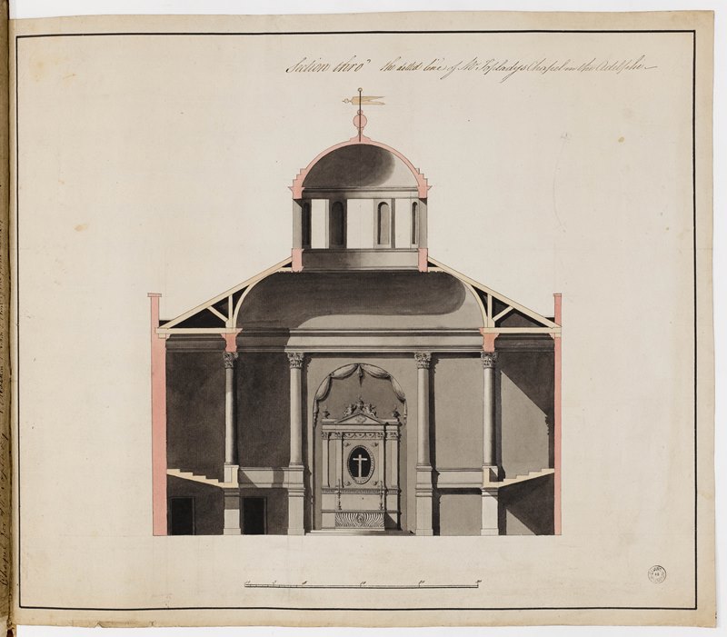 mblowfieldimage/jpeg90.93 KB
mblowfieldimage/jpeg90.93 KB
adelphi-adam-ceiling-garrick-victoria-and-albert.jpg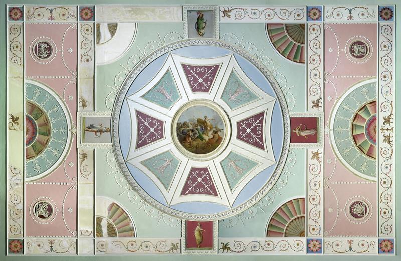 mblowfieldimage/jpeg97.26 KB
mblowfieldimage/jpeg97.26 KB
imagefield_gdk1ZO.jpeg dp_adminimage/jpeg4 KB
dp_adminimage/jpeg4 KB
miniture-georgian-houses.jpg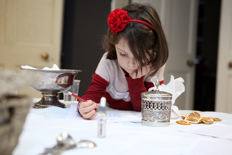 mblowfieldimage/jpeg163.49 KB
mblowfieldimage/jpeg163.49 KB
soane-parametricism.jpg mblowfieldimage/jpeg78.19 KB
mblowfieldimage/jpeg78.19 KB
soane-museum-parametricism.jpg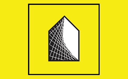 mblowfieldimage/jpeg23.19 KB
mblowfieldimage/jpeg23.19 KB
soane-museum-high-tech.jpg mblowfieldimage/jpeg64.71 KB
mblowfieldimage/jpeg64.71 KB
soane-high-tech.jpg mblowfieldimage/jpeg21.64 KB
mblowfieldimage/jpeg21.64 KB
metabolism-soane-museum.jpg mblowfieldimage/jpeg82.8 KB
mblowfieldimage/jpeg82.8 KB
soane-museum-metabolism.jpg mblowfieldimage/jpeg24.71 KB
mblowfieldimage/jpeg24.71 KB